Collections Item Detail
Article, Bergen Tunnel: A Special Type of Track Construction for Tunnels & Subways. Engineering News, Aug. 19, 1909.
2012.001.0169
2012.001
Purchase
Purchase
Museum Collections.
1909 - 1909
Date(s) Created: 1909 Date(s): 1909
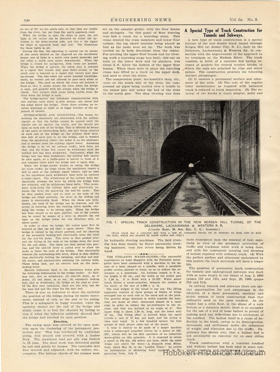
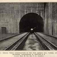
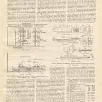
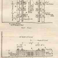
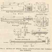
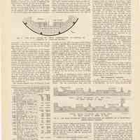
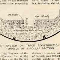
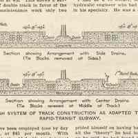
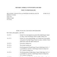
Notes: Archives 2012.001.0169 Transcription of article: A Special Type of Track Construction for Tunnels and Subways. Followed by Photo index of HAER report. ----- ENGINEERING NEWS. Vol. 62. No. 8. August 19, 1909. Pages 190-192. A Special Type of Track Construction for Tunnels and Subways. A new type of track construction is a special feature of the new double track tunnel through Bergen Hill (at Jersey City, N. J.), built by the Delaware, Lackawanna & Western Ry. in connection with the improvement of the approach to its terminals on the Hudson River. The track consists, in brief, of a concrete bed having recesses or pockets for treated wooden blocks, to which the rails are attached by clips and screw spikes. The construction presents the following distinct advantages: (1) It ensures a permanent surface and aline-ment [sic - alignment] of the rails. (2) The cost of the regular labor maintenance as required with ballasted track is reduced to track inspection. (3) The renewal of the blocks is much simpler, safer and ---- FIG. 1. SPECIAL TRACK CONSTRUCTION IN THE NEW BERGEN HILL TUNNEL OF THE DELAWARE, LACKAWANNA & WESTERN R. R. (Lincoln Bush, M. Am. Soc. C. E.; Inventor.) (Each track has a concrete bed with a row of creosoted blocks set in recesses on each side to hold the rails, which are secured by screw spikes and clips.) ---- more economical than the renewal of ties; especially in while work is being done, and with the consequent tamping and dressing of ballast required with ordinary track. (4) With the perfect surface and alinement maintained by this system the track materials will have a longer life. The question of permanent track construction for tunnels and underground railways was dealt with at some length in our issues of Aug. 2, 1906 (pages 113 and 123), and Sept. 20, 1906 (pages 310 and 314). In railway tunnels and subways there are special opportunities for "and advantages in the adoption of a more permanent, sanitary and stable system of track construction than that ordinarily used on the open roadbed. As the tunnel has a solid floor, in the shape of a rock bottom or a masonry invert, there is no necessity for the use of a bed of loose ballast to permit of making good any deflections due to settlement of the roadbed. The ballast itself is a cause of deflection in the track, owing to its disintegration, movement and settlement under the influences of weight and vibration due to the traffic. Experience has shown also, that a ballast bed is not necessarily an essential for an easy riding track. Track construction with a concrete roadbed and without ballast has been used in some submarine tunnels and underground railways, but we believe the Bergen Hill tunnel of the Dela- ==== page 192 ware, Lackawanna & Western Ry. is the first case in which this type of track ha-s been used in an ordinary railway tunnel. Fig. 1 is a view of the track at one of the open shafts in the tunnel. At the left is the old double-track tunnel. The new tunnel was opened for traffic Feb. 15, 1909. This track has proved very easy-riding for trains and passengers, with no objections from noise and vibration. It has been in service under heavy traffic for practically five months. The designer states that a very careful inspection made on July 8 shows that there has not been any movement whatever of the tie blocks, and no defects of any character could be found. One noticeable feature is that the tie-plates have not settled into or abraded the wood to any perceptible extent. The tunnel in question is 4,280 ft. long, driven through solid rock and lined with 2 ft. of concrete. It has a width of 30 ft. between vertical sides and a center height of 24 ft. 11 ins. from the base of the concrete bed to the crown of the semi-circular arch, with the floor of the tunnel ---- FIG. 2. CROSS SECTION OF SPECIAL TRACK CONSTRUCTION OF THE BERGEN HILL TUNNEL. [detail text in drawing not transcribed] ----- Upon the rock floor of the tunnel are two continuous beds of concrete, approximately 8 ft. wide and 20 ins. thick, with the concrete between the tie-blocks reinforced by. means of vertical rods against longitudinal stresses that may arise from the driving of wedges or creeping of track. Conduits for electric wires are embedded in the concrete, being thus conveniently and economically placed while reducing the quantity of concrete at a part of the roadbed which carries practically no load. The top of the concrete has a slope of in. per ft. each way from the center line, and is thus kept clear of the base of the rails. The lower part of the bed is composed of 1 part Portland cement to 12 parts of crushed stone and sand, large coarse stone also having been used to reduce the volume of concrete. The upper part is a 1:6 mixture of cement and Cow Bay (Long Island) gravel, mixed fairly wet. After the track was completed, the concrete was allowed to set for a month before the tunnel was opened to traffic. Along each side of the concrete bed are recesses or pockets about 22 ins. apart c. to c., to receive wooden blocks (A) which are held in place by anchor bolts (B), wedges (C) and a shoulder in the recess. The tops of the blocks are about m ins. above the surface of the concrete; steel tie-plates on these blocks support the rails. Upon the ends of the blocks are laid guard timbers 0x8 ins. This is a desirable protection with tracks carried above the floor in a railway tunnel having heavy traffic with heavy wheel loading, and where a slight deviation of a derailed train might cause it to strike the tunnel wall or foul a train on the adjacent track. The principal parts of the track are shown in detail in Fig. 3. The wooden blocks (A) are 30 ins. long, 8x8 ins. in section, dressed to 7 3/4 x 7 3/4 ins. They are notched at one side to make a dovetail fit in the pocket, which thus prevents any lateral movement. Bach block is secured to the concrete by a 7/8-in. anchor bolt (B), which is. fitted with a standard nut for a 1 1/4-in. bolt. Over the bolt is slipped a light tin tube or sleeve, when the concrete is being deposited, and the bolt is set in the concrete with its head flush with the top of the wooden block. When the concrete has set, the bolt is removed, a 3/8-in. washer is placed under its head, and the bolt is replaced and screwed into the nut. This arrangement provides for sufficient adjustment in the future by screwing the bolt down into the nut. T'he blocks, anchor bolts, wedges, etc., are set in place in the forms, and the concrete is deposited around them. A wooden wedge (C) is placed against one side to hold the block in position in the pocket, to take up lost motion due to shrinkage or wear, and to enable a tie-block to be replaced without raising the rail, interfering with traffic or disturbing the adjacent tie-block fastenings. The vertical filler (D) at the end of the wedge is removed whenever it becomes necessary to drive in the wedge, in order to take up any looseness due to shrinkage or wear. The filler and wedge are fastened to the block with light nails to hold them in position when concrete is being deposited, and each wedge is secured by a lag screw (E), which is put through the guard timber and extends about 2 ins. into the wedge. The guard timber is fastened to each block by a larger lag screw (P). The rail blocks and wedges are of long-leaf yellow pine, treated (after being dressed to shape) with 12 lbs. of creosote per cu. ft. On each block is a flat wrought-iron tie-plate (G) having four 15-16-in. holes for screw spikes. Only two of these holes are used at a time; the other two can be used should the wood become defective or a screw break at the first holes used. A modified design of plate for use where the guard rails are omitted, is made long enough to cover the wedge as well as the block, and has an additional 9-16-in. hole for a lag screw 1/2 x 2 3/4 ins. to hold the wedge. The screw spikes (H) which form the rail fastenings do not hold the rails direct by mushroom heads, but have standard scxuare heads and are fitted with square clips (J). The rail flange bears directly against the clip and does not wear or cut the screw spikes, as it would were it in direct contact with the spikes. These clips are cut from bars planed ta fit the rail flanges. The clips are 3/4-in. thick at intermediate blocks and 1-in. at the joints, the greater thickness giving the necessary extra height to hold the flange of the splice bar. Before the spike is screwed home, the thread is well greased or the hole filled with hot creosote oil. ---- FIG. 3. DETAILS OF SPECIAL TRACK CONSTRUCTION FOR TUNNELS AND SUBWAYS. [detail text in drawing not transcribed] ---- When a block is to be removed, a timber shim is placed on each side of the block between the rail and the top of the concrete, to support the weight of traffic on the rail. The fastenings are then removed. The wedge is then withdrawn, and the block is moved back until its larger end clears the shoulder of the pocket, so that it can be pulled out. This is done without disturbing ---- TABLE I.— ESTIMATE OF COST FOR ORDINARY BALLASTED TRACK IN THE NEW BERGEN HILL TUNNEL (4,280 FT.); DELAWARE, LACKAWANNA & WESTERN RY. 232 gross tons 91-lb. special open-hearth rail, .................at $34.00 $7,888.00 520 pairs of angle bars.........." 1.07 550.40 3,120 splice bolts ................." .03% 104.00 3,120 nut locks ...................." .009 28.08 8,835 tie plates, 6 x 9 X 1/2 in......." .131 1,157.38 520 joint tie-plates, 6 x 11 x 1/2-in. " .171 88.92 18,710 spikes ......................." .01 3/4 327.42 4,077 creosoted y. p. ties, 7x9 ins. 8 1/2 ft........................" 2.10 9,821.70 6,737 cu. yds. stone ballast, delivered " 1.00 0,737.00 17,970 lin. ft. of vitrified 6-hole conduits, 5% allowed for breakage " .225 4,014.00 5,720 yds. drilling for wrapping conduit joints .................. " .095 543.40 2,035 cu. yds. rock excavation for tile drains .................." 7.00 14,245.00 8,988 lin. ft. of 8-in. drain tile; 5% added for breakage.........." .085 703.97 2,000 cu. yds. of extra concrete for conduits ...................." 0.25 12,500.00 8,500 lin. ft. single track laying and surfacing ..................." .20 1,712.00 580 lin. ft. concrete voids, occupied by conduits, but charged for by contractor ............" 3.50 2,051.00 Total ............................. .......$62,508.87 Total, exclusive of conduits......... .......$43,429.87 Total per foot of double track: $14.62 including conduits; $10.15 exclusive of conduits. ==== page 192 the other block fastenings and without interfering with traffic. One man can easily make the renewal. With the ordinary type of track, a gang of men is required to renew ties and perform the necessary digging out and tamping of ballast. In a tunnel or subway this latter method of renewal's is a matter of difficulty and large relative expense, as well as of danger. The system of track construction described above is the invention of (and has been patented by) Mr. Lincoln Bush, M. Am. Soc. C. E., Consulting Engineer, New York, and we are indebted to him for drawings and information respecting ----- FIG. 4 THE BUSH SYSTEM OF TRACK CONSTRUCTION AS ADAPTED TO TUNNELS OF CIRCULAR SECTION. ---- this system. Mr. Bush was Chief Engineer of the Delaware, Lackawanna & Western Ry. at the time when its new terminal line and the Bergen Hill tunnel were built. The patents cover modifications of the general design, and also the application of the system to special classes of tunnels and 'subways. Fig. 4 shows the system adapted to a circular single-track tunnel of the type very generally used for submarine crossings. Fig. 5 shows two designs for the application of the system to a four-track subway or underground railway. In the upper design, the track drains are at the side of each track (as in the Bergen Hill tunnel), and enable the removal and renewal of the wooden blocks to be made from outside the track. In the lower design, the track drains are in the middle of each track, and the renewal of the blocks must be done from between the rails. Where such lines are operated by electricity on the third-rail system, every third or fourth block on one side can be made of extra length in order to carry the conductor rail. The concrete roadbed gives facilities for sweeping and flushing the floor to remove dust and refuse, and experience with underground rapid-transit railways has shown the necessity of thus cleaning the roadbed in order to avoid dust, unpleasant odors and unhygienic conditions. It is stated that creosoted timber for use in subways and "tube" tunnels should be piled and left exposed to summer sun and air for three or four months, in order to permit vapors to escape and thus avoid the heavy smell of the creosote oil. The estimated cost of the ordinary type of ballasted track for the Bergen Hill tunnel (4,280 ft.), including electric conduits and two lines of drainage trenches, with tile drains below bottom of ballast, was $62,569, or $43,430 exclusive of the electric conduits. This is equivalent to $14.62 and $10.15 per foot, respectively, of double track. The total actual cost of the track with concrete roadbed and electric conduits was $61,011, or $56,423 exclusive of the conduits; this is equivalent to $14.26 and $13.18 per foot, respectively, of double track. The greater cost of the conduit work with the ballasted track was due to the fact that it would have been necessary to cut rock channels in the side of the tunnel to receive the conduits, or place them in special construction along the side walls, below base of rail, while with the concrete roadbed system they were incorporated in the concrete. The details of cost of the two systems are given in Tables I. and II. A summary of comparative annual costs for concrete roadbed and ballasted track construction is given in Table III., the investment in each case being capitalized at 4%. This shows a saving $1.21 per foot of double track in favor of the former. For the maintenance work only two track inspectors have been employed (one by day and one at night), at $45 per month. With the ballasted track in the old double-track tunnel (which is paralleled by the new tunnel) the labor cost for the year 1908 was $565 per month, as follows: $75 for foreman, $400 for laborers and $90 for watchmen. ---- FIG. 5. THE BUSH SYSTEM OF TRACK CONSTRUCTION AS ADAPTED TO A FOUR-TRACK RAPID-TRANSIT SUBWAY. ---- TABLE II.—ACTUAL COST OF SPECIAL TRACK CONSTRUCTION WITH CONCRETE ROADBED IN THE NEW BERGEN HILL TUNNEL (4,280 FT.); DELAWARE, LACKAWANNA & WESTERN RY. 232 gross tons 01-lb. special open- $7,888.00 hearth rail ..................at $34.00 250 pairs of angle bars..........." 1.07 556.40 3,120 splice bolts ................." .03 1/3 104.00 3.120 nut locks ...................." .000 28.08 8,835 tie-plates, 6 x 9 x 1/2-in......." .131 1,157.38 520 joint tie-plates, 6 x 11 x 1/2-in. " .171 88.92 17,976 lin. ft. vitrified 6-hole conduit, 4,044.60 5% allowed for breakage......" .225 5,720 yds. drilling for wrapping con- .095 543.40 duit joints .................." 9,360 creosoted y. p. tie blocks, 8x8 5,616.00 x 30 ins...................." 45.00 9,360 creosoted y. p. wedges, 2 1/4 x 1,579.50 8 x 30 ins...................." 45.00 17.680 intermediate rail clips........" .039 689.52 18,720 pieces round iron 1 x 15 ins. for .06% 1,185.60 1,010 joint rail clips..............." .051 53.04 18,720 lag screwspikes, 7/8 x 7 1/2 ins.. " .046 861.12 9,360 lag screws for guard rail, 318.24 3/4 x 11 ins..................." .034 9,360 washers for guard rail, 3/8 x 280.80 3 ins........................" .03 9,360 wedge lag screws. 1/2 x 7 ins. " .013 121.68 18,555 lin. ft. of y. p. creosoted guard 2,783.25 rail, 5x8 ins................" 45.00 4,680 guard rail anchor bolts, 7/8 x 405.60 18 ins......................" 08% 4,680 guard rail washers, 3/8 x 3 ins. " .03 140.40 4,680 anchor nuts, 2 1/4 ins. sa. x 1 1/4 374.40 .08 4,680 tin tubes for anchor bolts.... " .005 23.40 3,754.4 cu. yds. concrete............" 6.25 23,465.00 1,019.2 cu. yds. concrete voids, occupied by tie blocks, wedges and conduits, but charged for by 3,567.20 3.50 Labor and engineering for assembling and fastening complete, tie blocks, wedges, guard rails, rail, rail joints, screws, screw spikes, etc., 8,560 lin. ft....." .60 5,136.00 $61,011.53 Total, exclusive of conduits........ $56,423.53 Total per foot of double track: $14.26 including conduits; $13.18 exclusive of conduits. ----- TABLE III.—COMPARATIVE ANNUAL COST. Interest on in- Track Total Type of track. vest- main- per ment. tenance. Total. mile. Concrete roadbed: With conduits____($61,011) $2,410 $1,080 $3,520 $4,344 Without conduits. ($56,423) 2,257 1,080 3,337 4,118 Ballasted track. With conduits____($62,560) 2,503 6,780 9,283 11,451 Without conduits. ($43,430) 1,737 6,780 8,517 10,507 [end article] ===== ===== For reference use, text of photo index for HAER NJ-137: HISTORIC AMERICAN ENGINEERING RECORD INDEX TO PHOTOGRAPHS DELAWARE, LACKAWANNA & WESTERN RAILROAD, SOUTH HAER NJ-137 BERGEN TUNNEL Jersey City Hudson County New Jersey INDEX TO BLACK AND WHITE PHOTOGRAPHS Rob Tucher, photographer, April 2001 NJ-137-1 General View showing the east portal of the South Bergen Tunnel in context, with North Bergen Tunnel to right, looking west NJ-137-2 General view from railroad bridge over Conrail tracks showing the west portal of the South Bergen Tunnel in context, with the Conrail tunnel below and to the right, looking east NJ-137-3 East portal, looking west NJ-137-4 West portal, looking east NJ-137-5 East-facing portal of South Bergen Tunnel within Open Cut No. 1 ( see HAER No. NJ-136-5. North Bergen Tunnel, for Open Cut No. 1 context), looking west NJ-137-6 West-facing portal of South Bergen Tunnel within Open Cut No. 1 ( see HAER No. NJ-136-5. North Bergen Tunnel, for Open Cut No. 1 context), looking east NJ-137-7 East-facing portals within Open Cut No. 2 (South Bergen Tunnel on left, North Bergen Tunnel [see HAER No. NJ-136] on right), from the South Bergen Tunnel tracks, looking west DELAWARE, LACKAWANNA & WESTERN RAILROAD, HAERNJ-137 INDEX TO PHOTOGRAPHS (Page 2) NJ-137-8 West-facing portals within Open Cut No. 2 (South Bergen Tunnel on right, North Bergen Tunnel [ see HAER No. NJ-136]) on left), from within the opposite portal of the South Bergen Tunnel, looking east NJ-137-9 Detail of east portal concrete, scored voussoirs, and concrete sidewalls and arch, looking southwest NJ-137-10 Detail of east portal concrete pier, with "D.L.& W. 1908" incised in its face, looking west NJ-137-11 General view of Shaft No. 1 in context, looking east NJ-137-12 ShaftNo. 1 looking northwest NJ-137-13 Open Cut No. 1, looking east NJ-137-14 General view of ShaftNo. 3 in context, looking northwest NJ-137-15 Open Cut No. 2, looking east NJ-137-16 General view of ShaftNo. 3 in context, looking northwest NJ-137-17 ShaftNo. 3, looking south NJ-137-18 "D.L.&W. R.R. Profile for New Tunnel Through Bergen Hill" Plan Sheet. December 1, 1905. On file at New Jersey Transit Corporation Headquarters, Newark, New Jersey NJ-137-19 "D.L.&W. R.R. New Bergen Tunnel...Details of Shaft..." Plan Sheet. October 30, 1908. On file at New Jersey Transit Corporation Headquarters, Newark, New Jersey NJ-137-20 "D.L.&W. R.R. New Bergen Tunnel...Detail of Open Cut Masonry..." Plan Sheet. Revised December 22, 1906. On file at New Jersey Transit Corporation Headquarters, Newark, New Jersey NJ-137-21 "D.L.&W. R.R. New Bergen Tunnel...Detail of Portal Masonry..." Plan Sheet. Revised December 22, 1906. On file at New Jersey Transit Corporation Headquarters, Newark, New Jersey ==== Status: OK Status By: dw Status Date: 2012-10-04
