Collections Item Detail
Article: Hillside Railroad Loop Line, Hoboken, N.J. Published in The Engineering Record, June 2, 1894.
2012.001.0209
2012.001
Purchase
Purchase
Museum Collections.
1894 - 1894
Date(s) Created: 1894 Date(s): 1894
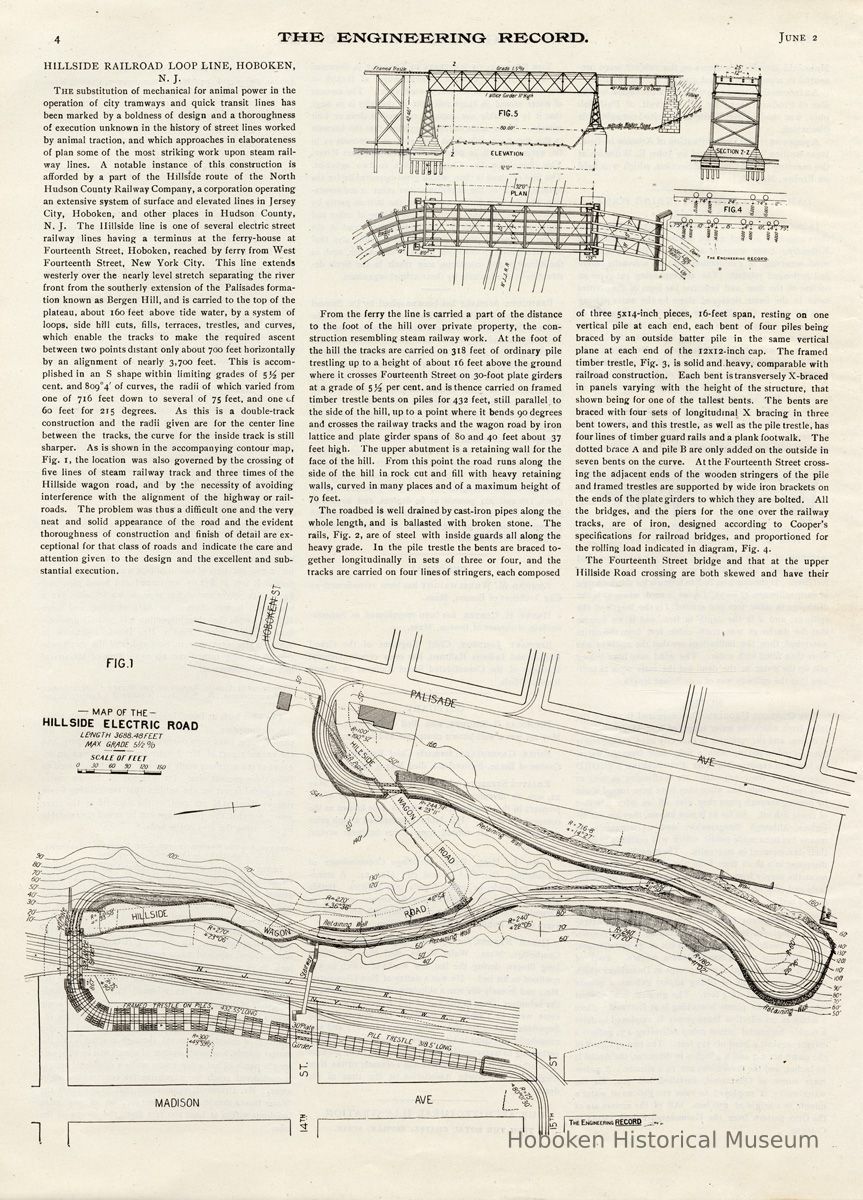
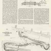
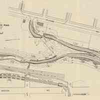
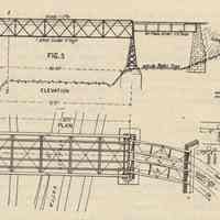
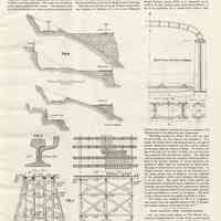
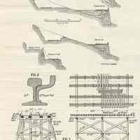
Notes: Archives 2012.001.0209 THE ENGINEERING RECORD June 2, 1894 pages 4-5 HILLSIDE RAILROAD LOOP LINE, HOBOKEN, N. J. The substitution of mechanical for animal power in the operation of city tramways and quick transit lines has been marked by a boldness of design and a thoroughness of execution unknown in the history of street lines worked by animal traction, and which approaches in elaborateness of plan some of the most striking work upon steam railway lines. A notable instance of this construction is afforded by a part of the Hillside route of the North Hudson County Railway Company, a corporation operating an extensive system of surface and elevated lines in Jersey City, Hoboken, and other places in Hudson County, N. J. The Hillside line is one of several electric street railway lines having a terminus at the ferry-house at Fourteenth Street, Hoboken, reached by ferry from West Fourteenth Street, New York City. This line extends westerly over the nearly level stretch separating the river front from the southerly extension of the Palisades formation known as Bergen Hill, and is carried to the top of the plateau, about 160 feet above tide water, by a system of loops, side hill cuts, fills, terraces, trestles, and curves, which enable the tracks to make the required ascent between two points distant only about 700 feet horizontally by an alignment of nearly 3,700 feet. This is accomplished in an S shape within limiting grades of per cent, and 809°4' of curves, the radii of which varied from one of 716 feet down to several of 75 feet, and one of 60 feet for 215 degrees. As this is a double-track construction and the radii given are for the center line between the tracks, the curve for the inside track is still sharper. As is shown in the accompanying contour map, Fig. 1, the location was also governed by the crossing ot five lines of steam railway track and three times of the Hillside wagon road, and by the necessity of avoiding interference with the alignment of the highway or railroads. The problem was thus a difficult one and the very neat and solid appearance of the road and the evident thoroughness of construction and finish of detail are exceptional for that class of roads and indicate the care and attention given to the design and the excellent and substantial execution. From the ferry the line is carried a part of the distance to the foot of the hill over private property, the construction resembling steam railway work. At the foot of the hill the tracks are carried on 318 feet of ordinary pile trestling up to a height of about 16 feet above the ground where it crosses Fourteenth Street on 30-foot plate girders at a grade of 5-1/2 per cent, and is thence carried on framed timber trestle bents on piles for 432 feet, still parallel to the side of the hill, up to a point where it bends 90 degrees and crosses the railway tracks and the wagon road by iron lattice and plate girder spans of 80 and 40 feet about 37 feet high. The upper abutment is a retaining wall for the face of the hill. From this point the road runs along the side of the hill in rock cut and fill with heavy retaining walls, curved in many places and of a maximum height of 70 feet. The roadbed is well drained by cast-iron pipes along the whole length, and is ballasted with broken stone. The rails, Fig. 2, are of steel with inside guards all along the heavy grade. In the pile trestle the bents are braced together longitudinally in sets of three or four, and the tracks are carried on four lines of stringers, each composed the hill, up to a point where it bends 90 degrees and crosses the railway tracks and the wagon road by iron lattice and plate girder spans of 80 and 40 feet about 37 feet high. The upper abutment is a retaining wall for the face of the hill. From this point the road runs along the side of the hill in rock cut and fill with heavy retaining walls, curved in many places and of a maximum height of 70 feet. The roadbed is well drained by cast-iron pipes along the whole length, and is ballasted with broken stone. The rails, Fig. 2, are of steel with inside guards all along the heavy grade. In the pile trestle the bents are braced together longitudinally in sets of three or four, and the tracks are carried on four lines of stringers, each composed of three 5x14-inch pieces, 16-feet span, resting on one vertical pile at each end, each bent of four piles being braced by an outside batter pile in the same vertical plane at each end of the 12x12-inch cap. The framed timber trestle, Fig. 3, is solid and.heavy, comparable with railroad construction. Each bent is transversely X-braced in panels varying with the height of the structure, that shown being for one of the tallest bents. The bents are braced with four sets of longitudinal X bracing in three bent towers, and this trestle, as well as the pile trestle, has four lines of timber guard rails and a plank footwalk. The dotted brace A and pile B are only added on the outside in seven bents on the curve. At the Fourteenth Street crossing the adjacent ends of the wooden stringers of the pile and framed trestles are supported by wide iron brackets on the ends of the plate girders to which they are bolted. All the bridges, and the piers for the one over the railway tracks, are of iron, designed according to Cooper's specifications for railroad bridges, and proportioned for the rolling load indicated in diagram, Fig. 4. The Fourteenth Street bridge and that at the upper Hillside Road crossing are both skewed and have their ---- Figure 4 and 5 top right corner ---- Figure 1, bottom half of page: — MAP OF THE- HILLSIDE ELECTRIC ROAD LENGTH 3688.48FEET MAX GRADE 5 1/2% -- SCALE OF FEET 0 30 60 30 120 150 ==== girders set at a slope of 5 to 100. The former has trestle and the latter masonry supports. In both cases each track is supported by a separate independent pair of plate girders, spaced 5 feet apart and united by vertical angle X braces and perpendicular and diagonal horizontal lateral bracing angles. Figure 5 shows the railway and adjacent highway crossing and indicates the general features of design and arrangement. Figure 6 shows characteristic cross-sections of roadbed, retaining walls, etc. The tracks are of standard gauge and are spaced 12 feet centers. The conductor wire is carried by bracket arms from iron pole standards placed between the two tracks. Short four-wheeled electric cars are operated by the underrunning trolley. The power for operating this road comes from the Hudson electric light station. The plant consists of two vertical compound engines built by the Philadelphia Corliss Engine Company, each being of 500 horse-power. There is a 1,000 horse-power cross-compound engine of the same make and two Macintosh & Seymour engines, each of 300 horsepower. The boiler plant consists of eight horizontal return-flue tubular boilers, each 6 feet in diameter and 16 feet long. The road was built for the North Hudson County Railway Company, of Hoboken, N. J., at a cost of $120,000 or that portion shown in Fig. 1. Charles B. Brush, M. Am. Soc. C. E., was Chief Engineer and Myles Tierney, of New York, was the contractor. --- Figures, 2, 3 and 6: Hillside Railroad Loop Line, Hoboken, N.J. ==== Status: OK Status By: dw Status Date: 2012-12-12
