Collections Item Detail
Brochure: The Holland Tunnel. Effective Nov. 13, 1927. Toll Rates. Traffic Regulations. Description of Tunnel.
2012.007.0013
2012.007
Lukacs, Claire
Gift
Museum Collections. Gift of a Friend of the Museum.
1927 - 1927
Date(s) Created: 1937 Date(s): 1927
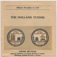
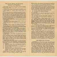
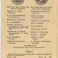
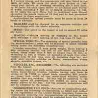
Notes: 2012.007.0013 Text of brochure issued for opening of The Holland Tunnel, November 1927. (page [1], cover as folded) Effective November 13, 1927 THE HOLLAND TUNNEL [color depictions of the cross section of two tubes] CROSS SECTION External Diameter of Tunnel 29 Feet, 6 Inches. Maximum Section 30 Feet, 4 Inches. TOLL RATES TRAFFIC REGULATIONS DESCRIPTION OF TUNNEL Rates and Regulations sub- ject to change without notice Office of the Superintendent - Administration Building, Canal and Varick Streets, New York City (page 2) [seal of the New York Commission] New York State Bridge & Tunnel Commission and New Jersey Interstate Bridge & Tunnel Commission New York State Bridge and Tunnel Commission GEORGE R. DYER, Chairman E. W. BLOOMINGDALE, Vice-Chairman McDOUGALL HAWKES A. J. SHAMBERG ALBERT GOLDMAN, Commissioner of Plant and Structures of New York City FREDERICK S. GREENE, Superintendent of Public Works PAUL WINDELS, Counsel MORRIS M. FROHLICH, Secretary [seal of the New Jersey Commission] New Jersey Interstate Bridge and Tunnel Commission THEODORE BOETTGER, Chairman JOHN B. KATES, Vice-Chairman THOMAS J. S. BARLOW JOHN F. BOYLE ISAAC FERRIS WELLER H. NOYES ROBERT S. SINCLAIR FRANK L. SUPLEE ROBERT CAREY, Counsel E. MORGAN BARRADALE, Secretary OLE SINGSTAD Chief Engineer and Acting Superintendent TOLLS The following toll rates shall apply to and be collected for vehicles, as designated: Vehicle Type Group No. Rate Motorcycle I $0.25 Passenger Automobile, with a capacity up to 7 passengers, ambulance or hearse II 0.50 Bus (Up to and including 29 passenger seating capacity) III 1.00 Truck (Up to 2 tons)** IV 0.50 2 Ton + to 5 Ton Truck V 0.75 5 Ton + to 10 Ton Truck VI 1.00 Trucks exceeding 10 Tons capacity and not exceeding 15 Tons Gross Weight nor exceeding 12 Tons Axle Load VII 2.00 Vehicles admitted by Special Permit, only VIII Special* For Bus exceeding 29 passenger seating capacity - apply for rates. 2 (page 3) Tolls, Speed, Spacing, Special Permits, Exclusions and Regulations **Toll Rates are based on the truck's carrying capacity. Trucks loaded beyond rated capacity shall pay according to actual load carried. Vehicle Weight, Carrying Capacity and Gross Weight must be displayed prominently on all trucks as required by law. *TOLL RATES for vehicles under special permit as follows: Survey charge $10 and, in addition, for permit if issued a flat rate of $2 plus 25 cents for each additional ton or frac- tional part thereof, in excess of 15 tons; or in addition to the $ 10 survey charge and the appropriate toll rate, listed in the table of tolls, 10 cents for each three inches or frac- tional part thereof of overhang exceeding the 9 inch limit; or 10 cents for each three inches or fractional part thereof of width exceeding 8 feet or of height exceeding 12 feet; or 10 cents for each three feet or fractional part thereof exceeding the length limits of 30 feet and 46 feet prescribed elsewhere in these regulations. Applications for special permits must be made at least 24 hours in advance. TRAILERS shall be charged for as separate vehicles and in accordance with the above schedule. SPEED - The speed in the tunnel is not to exceed 30 miles per hour. SPACING - Vehicles moving or standing in the tunnel shall maintain a clear spacing of not less than 75 feet. SPECIAL PERMITS - The obtaining of special permits from the superintendent's office will be required to admit vehicles falling under the following classifications: Vehicles exceeding 15 tons gross weight, those having a side overhang beyond the rim of the wheel exceeding 9 inches, those wider than 8 feet or longer than 30 feet, or exceeding 12 feet in height, all inclusive of load, four-wheel trailers over 46 feet long, over all, including draw bar, and such slow moving vehicles as floats, steamrollers, steam shovels, movable cranes, etc. VEHICLES, ETC., EXCLUDED - The following are excluded from the tunnel: Bicycles, hand and push carts, wheelbarrows, double-deck buses, horse-drawn vehicles, vehicles having axle loads in excess of 12 TONS or wheel loads exceeding 800 pounds per linear inch width of tire, metal-tired vehicles, motor vehicles that are smoking. No bus will be admitted to the tunnel unless all passengers are seated on seats perma- nently affixed to the bus. For the present, pedestrians will not be admitted to the tunnel. COMMODITIES EXCLUDED - Articles or commodities fall- ing under the following classifications, as listed and defined in the regulations of the United States Interstate Commerce Commission covering the transportation of explosives and other dangerous articles, shall be excluded from the Tunnel. 1. Explosives. 2. Dangerous articles other than explosives, as follows: (a) Inflammable liquids (these give off inflammable va- pors at ordinary temperatures). (b) Corrosive liquids (these include the well known power- ful mineral acids). (c) Compressed gases of a poisonous nature. (d) Poison gases or liquids (those gases which are highly poisonous when present in the air even in small pro- portions and those liquids which give off highly poisonous vapors at ordinary temperatures). Furthermore, loose hay, straw or other material in like condition which is ordinarily combustible will not be admitted; nor reserve gasoline exceeding 1 gallon. 3 (page 4) REGULATIONS FOR DRIVERS AND OWNERS OF VEHICLES (1) No operator who is physically incapable of operat- ing his vehicle will be permitted to enter the tunnel. (2) No vehicle which is so loaded or constructed as to seriously retard traffic or injure persons or damage property will be permitted to enter the tunnel. (Baled hay, or straw or other inflammable material must be covered with tar- paulin.) In special cases however admission may be ob- tained through special permit by the superintendent. (3) No tire changes may be made in the tunnel. (4) Smoking in the tunnel is prohibited. (5) No vehicle may leave its line except as so directed by a policeman. Drivers' attention is called to signs posted at New York City exit at Canal Street; also to City police regulation of traffic at this point. (6) The use of cut-outs, horns, sirens, whistles and any other noise making device in the tunnel is prohibited. (7) All vehicle head lights must be extinguished upon entering the tunnel. (8) SIGNAL LIGHTS-GREEN SIGNAL LIGHT indicates that traffic lanes are clear and that traffic may pro- ceed. RED SIGNAL LIGHT indicates that traffic must halt. Engines will not be permitted to race at a halt. "STOP ENGINE" SIGNAL indicates that ALL ENGINES MUST BE STOPPED AT ONCE and shall remain so until the green light is again displayed for resumption of travel. YELLOW SIGNAL LIGHTS indicate that all traffic shall move in right hand lane only. (9) Brokendown [broken down] Vehicles, etc. (a) Gasoline will be supplied to a car running out of gasoline in the tunnel at $1.00 per gallon. This will be payable to the officer upon delivering the gasoline. (b) Cars breaking down in the tunnel and requiring the use of the tunnel emergency towing equipment will be towed out into the exit plaza. The charge for such services, double the regular toll rate, is payable to the sergeant in charge of emergency truck. (10) Any person who through gross carelessness, reck- lessness or without due regard for the safety of persons or property, violates the traffic rules of the Commissions or endangers the safety of persons or property, shall be re- ported by the Department of Police to the Superintendent. Thereafter a notice shall be served upon such violator that at a specified time and place a hearing will be held, at which he is invited to attend and show cause why he should not be barred from using the tunnel for a period to be designated by the Commissions. Such hearing shall be held before the Superintendent or a member of his staff designated by him, and a report of his findings and rec- ommendations shall be transmitted to the Commissions. THE HOLLAND TUNNEL AUTHORITY - In 1919, the New York State Bridge and Tunnel Commission and the New Jersey Interstate Bridge and Tunnel Commission were authorized by the legislatures of their respective states to co-operate and enter into a con- tract with each other for the joint construction, operation, repair and maintenance of a tunnel between Manhattan, in the vicinity of Canal Street, and a point in Jersey City. CLIFFORD M. HOLLAND, FIRST CHIEF ENGINEER - These Commissions unanimously appointed Clifford M. Hol- land, of Brooklyn, New York, their Chief Engineer. Mr. Holland assumed his office on July 1, 1919, and carried on the work of planning and constructing the tunnel up to the time of his death, October 27, 1924. Mr. Holland was suc- ceeded as Chief Engineer by Mr. Milton H. Freeman, the Engineer of Construction. He also died less than five months after Mr. Holland's death, and was succeeded by the present Chief Engineer, who up to that time had been the Engineer 4 (page 5) of Designs. It was in Mr. Holland's honor that the tunnel has been named "THE HOLLAND TUNNEL." CONSTRUCTION CONTRACTS - Ground was broken for the first contract, the New York land shafts, on October 12, 1920, since which date there have been twenty-two construc- tion and equipment contracts let and brought to completion by the Commissions. Half of the expense of construction and maintenance is borne by each State. The embellishment of the entrances and exits, including the lining of the pres- ent concrete walls with granite masonry, will be cared for by two contracts still to be let, preparation of which is now in progress. The tolls collected will finance the operation and maintenance of the Tunnel and in time repay the two Stages for their expenditures. The total cost of the Tunnel will be forty-eight million, four hundred thousand dollars. WORK UNDER COMPRESSED AIR - The driving of the tunnels by means of shields underneath the bed of the Hud- son River and the sinking of the seven shafts and thirty caissons for building foundations were accomplished by means of compressed air which balanced the pressures on the outside of these structures and held the river water out, which otherwise would have seeped down through the river mud or silt and penetrated the working chambers of the shaft caissons and the tunnel headings. While the greater part of the under-river tubes were driven through silt, a stretch of nearly 1000 feet near the New York pierhead line was driven through ledge rock. It is in this rock that the pump chamber and sump for collecting any water that might flow in the tunnel roadway, are located, at the lowest point. Four of the principal contracts covered this part of the construction, which proceeded almost continuously from June 27, 1921, to the date of the discontinuance of the use of compressed air, May 8, 1926. The maximum pressure required was for the New Jersey river shafts and was 47% pounds per square inch above atmosphere. During this five year period 756,565 decompressions took place, of men coming out of the compressed air work, and the care taken in spending the full times for decompressions accounts for the low number of cases of "bends," or caisson disease, which totalled but 528, or a percentage of less than 7/100 of one percent, no fatality having occurred which was directly attributable to caisson disease. THE TUNNEL - The cover page shows the two tubes com- prising The Holland Tunnel while its location and statistics are shown respectively on the plan and profile plate, and in the table at the end of this pamphlet. The north tube is to accommodate west-bound traffic, en- tering the New York Entrance Plaza between Hudson and Varick and Broome and Watts Streets, in New York, while the south tube serves east bound traffic, entering at Twelfth and Provost Streets, Jersey City. The exit in each City is located some distance from the entrance, being at Canal and Varick Streets, alongside the Administration Building in New York, and at Fourteenth and Provost Streets, Jersey City, next to the New Jersey Administration Building. This separation of exit from entrance is to prevent undue traffic congestion in the city streets, in the immediate vicinity of the tunnel. Each tube is built of cast-iron segments bolted together, forming a ring of 29 feet, 6 inch outside diameter. This is lined on the inside with concrete, forming the road- way supports, sidewalk and sides. ROADWAY - The roadway in each tube, accommodating two lines of traffic, is of granite block, with granite curbs. It is estimated that an average of 1900 motor vehicles can pass through each tube per hour. VENTILATION - The air in the tunnel can be completely changed in a little less than one and one-half minutes, or 42 times per hour. The space below the roadway conducts fresh air from the blower fans in the nearest ventilation building, and the simi- lar space above the ceiling leads the vitiated air away whence it is exhausted by exhaust fans in the same building. There are 84 of these blower and exhaust fans provided, with an allowance of one-third of their number being held 5 (page 6) constantly in reserve. The four ventilation buildings house these fans and the electric motors which drive them, together with all the necessary auxiliary apparatus and equipment. The fresh air in the tunnel is led by side ports from below the roadway where it travels longitudinally, to an "expansion chamber" which extends on either side a little above the curb. A continuous slit allows the air to escape into the tunnel from this expansion chamber whence it passes through the exhaust ports in the ceiling, so that there is no move- ment of air lengthwise in the tunnel roadway portion; gases from automobiles are thus diluted before exhaustion. The installed horsepower for the fan equipment amounts to about 6000 horsepower, of which about 4000 horsepower will be required to ventilate the tunnel at maximum capacity. The method of ventilating The Holland Tunnel and the design of the ventilating equipment were based upon an exhaustive series of original tests and investigations carried on from December, 1919, to October, 1922. The problem was unprecedented and data lacking, there- fore, in November, 1919, the New York and New Jersey Bridge and Tunnel Commissions, through their Chief En- gineer, sought and obtained the hearty co-operation of,the United States Bureau of Mines in undertaking this investi- gational and experimental work. The Bureau agreed to furnish technical directors and facilities of several of their stations, while the Tunnel Commissions agreed to fur- nish funds for securing technical assistants, labor, etc. Later the University of Illinois became a third party to the agreement and factors for power determination were ob- tained by experiments made from February, 1921, until Octo- ber, 1922, at the Engineering Experiment Station, on model air ducts of concrete and sheet metal. The investigations covered four main subdivisions: Mature and quantity of gases emitted by motor vehicles under usual road operation conditions; the physiological effects of the gases, particularly carbon monoxide; tests both as to the method of admitting and exhausting the air and the determination of the value of the friction of air flowing in concrete conduits, whence the power necessary, in any given case, could be accurately calculated. The physiological tests were made at Yale University and confirmed in the Bureau's "experimental mine" near Pittsburgh where the method of ventilation was also confirmed after tests. These results have since been successfully applied, not- ably in the design and ultimate construction of the Liberty Tunnel of Pittsburgh, Pennsylvania, and in the building of the Estuary Tunnel of Oakland, California. POWER SUPPLY - The electric current for operating the ventilation equipment and lighting of the tunnel is obtained from both sides of the Hudson River. On each side current is available from three independent cables any one of which can be fed from either of two generating sources, making a total of four independent generating sources served by six independent cables. Each cable is of sufficient capacity to carry the full tunnel load, thereby providing adequate insurance against power failure. TUNNEL LIGHTING - The lights in the tunnels' sidewalls are normally placed about 20 feet apart along the tunnel. At the portals and for a short distance within, this spacing is reduced in order to provide greater illumination at these points to counteract the sudden transition from daylight into the artificial lighting of the tunnel. The two main sources of power serve alternate lights, so that the failure of one source of power will leave half of the lights still illuminating the roadway. SUPERVISORY CONTROL - In addition to a subsidiary control board in each of the four ventilation buildings, from which all equipment in that building can be operated, there is a central supervisory control board located in the top floor of the New York Administration Building from which board all equipment in the entire tunnel project can likewise be operated by the Chief Operator. 6 (page 7) MISCELLANEOUS TUNNEL DATA - The principal data concerning The Holland Tunnel are to be found below. Five shields were employed in driving the tunnels, two starting from the bottom of the New York land shafts and working their way, one for each tube, westward, through the streets and under the bulkhead wall of Manhattan out into the rock reef at the pierhead line and through the river shaft previously sunk into the rock; two from the bottom of the New Jersey land shafts working eastward through the New Jersey river shafts and across the river, meeting the westbound shields and joining with them in the rock. A fifth shield used in driving the south tunnel west, under the Erie Railroad yard, was rebuilt to drive the north tunnel west 30 feet, 4 inches in diameter, which is the largest shield-driven tunnel ever built. Emergency exits, leading from one tunnel to the adjacent tunnel as well as to the surface at the shafts, are designated by signs. The tile lining of the tunnel was carefully specified as to its quality and the requirements were unusually strict. These were fixed after extended experimentation to produce a tile that would withstand the temperature and atmos- pheric changes to be encountered in the tunnel, throughout the changing seasons. Along the tunnel walls at convenient intervals occur va- rious niches to accommodate fire fighting apparatus, hose for flushing and fire purposes, valves easily accessible, connected with the six-inch water main traversing each tunnel, sand bins, and telephone and relay niches. These are enclosed by bronze doors. The distances from the entrance portals of each tunnel are designated by mosaic tile bands at the % mile points and the state line is specially so marked. TUNNEL DATA TUNNEL LENGTHS Total length of tunnel 9250 feet between portals 8463 feet Distance between river shafts 3374 feet Length of under-river portion 5480 feet CAPACITY Number of Roadways 2 Roadway widths 20 feet Head room 13 feet, 6 inches Estimated hourly capacity (in both directions) 3,800 vehicles Estimated maximum daily traffic 46,000 vehicles Estimated yearly traffic 15,000,000 vehicles Maximum up-grade 3.8 per cent Maximum down-grade 4.06 per cent CONSTRUCTION DATA Maximum depth, top of tunnel below mean high water 72 feet Maximum depth of roadway below mean high water 93 feet Quantities: Tunnel Excavation 500,000 cu. yards Cast-iron tunnel lining 115,000 tons Tunnel concrete 130,000 cu. yards Cost $48,400,000 VENTILATION Method: Transverse distributed. Air will be discharged and removed continuously throughout the length of the tun- nel-no longitudinal movement of air. Ventilation provides for changing air 42 times per hour. Total amount of fresh air to be supplied to the tunnel per minute - 3,761,000 cu. ft. Carbon monoxide to be limited to 4 parts in 10,000 parts of air. [end text] (page [8], back cover as folded) The Holland Tunnel Plan [color illustration] Profile [color illustration] Status: OK Status By: dw Status Date: 2012-02-15
![pg [1] cover, as folded](https://d8e7jbdw4fu0e.cloudfront.net/11047/9e02bf50-fadd-11ed-a641-b3912f9925a9-utuv65x.lg@2x.jpg)

![pg [1] cover, as folded](https://d3f1jyudfg58oi.cloudfront.net/11047/image/9e02bf50-fadd-11ed-a641-b3912f9925a9-uFg8G7e.tn.jpg)
![unfolded: outside, from left, pp. 6-[8] + pg [1] cover](https://d3f1jyudfg58oi.cloudfront.net/11047/image/9f34fdc0-fadd-11ed-a641-b3912f9925a9-uFg8HGq.tn.jpg)
![detail pg [8] The Holland Tunnel, Plan, Profile (color); back as folded](https://d3f1jyudfg58oi.cloudfront.net/11047/image/a8beb3e0-fadd-11ed-a641-b3912f9925a9-uFg8LHl.tn.jpg)
![detail pg [8], rotated, enlarged](https://d3f1jyudfg58oi.cloudfront.net/11047/image/a9f02f00-fadd-11ed-a641-b3912f9925a9-uFg8Ldz.tn.jpg)
