Collections Item Detail
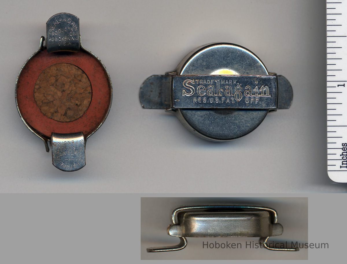
Bottle stopper manufactured by Seal-Again Products Co., Hoboken. N.J., ca. 1919-1924.
2012.007.0057
2012.007
Lukacs, Claire
Gift
Museum Collections. Gift of a Friend of the Museum.
1919 - 1924
Date: 1919-1924
Good
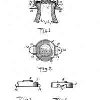
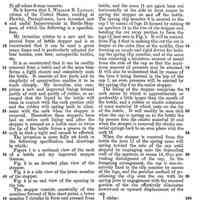
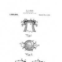
Notes: W. B. LANGAN. BOTTLE STOPPER, APPLICATION FILED AUG. 17, 1918. [U.S. Patent] 1,324,256 Patented Dec. 9, 1919. UNITED STATES PATENT OFFICE WILLIAM B. LANGAN, OF HAWLEY, PENNSYLVANIA, ASSIGNOR TO KOSCHERAK SIPHON BOTTLE. WORKS, OF HOBOKEN, NEW JERSEY, A CORPORATION OF NEW JERSEY. BOTTLE-STOPPER. 1,324,256. Specification of letters Patent. Patented Dec. 9, 1919. Application filed August 17, 1918. Serial No. 250,369. To all whom it may concern: Be it known that I, William B. Langan, citizen of the United States, residing at Hawley, Pennsylvania, have invented new and useful Improvements in Bottle-Stoppers, of which the following is a specification. My invention relates to a new and improved form of bottle stopper and is so constructed that it can be used a great many times and is particularly adapted for beer bottles, root beer, sarsaparilla bottles, etc. It is so constructed that it can be readily removed from a bottle and at the same time forms a tight closure and completely seals the bottle. It consists of few parts and its simplicity of construction enables it to be made cheaply. My invention also comprises a new and improved lining formed partly of cork and partly of rubber, so arranged that the liquid in the bottle will come in contact with the cork portion only and the rubber will spring back in aline-ment with the cork when the stopper is removed. Heretofore these stoppers have had an entire cork lining and after the stopper is pressed on a bottle once or twice the lip of the bottle forms a groove in the cork so that a tight seal cannot be effected. The invention is more fully set forth in the following specification and drawings in which: (Figure 1 is a sectional view: of the neck of a bottle and my improved stopper thereon. Fig. 2 is an inverted plan view of the stopper. Fig. 3 is a side view of the lower member of the stopper. Fig. 4 is an end view of the opening in the rim. The stopper consists essentially of two members formed of thin sheet metal, a lower member 7 circular in form and pressed from thin sheet metal. The lower member 7 has a projection or boss 8 stamped therein. The lower member 7 is secured to the top of the bottle by means of a spring clip 9, best shown in Fig. 1. This clip 9 consists of a straight piece of metal extending across the top of the stopper and having downwardly bent spring arms 10 bent in to form jaws or gripping members 11 to fit tightly around the outer side and underneath the lip of the bottle, and the arms 11 are again bent out horizontally at the side to form means to spring the stopper on and off the bottle. The spring clip member 9 is secured to the cap 7 by means of lugs 13 formed by cutting an aperture 14 in the rim of the stopper and bending the cut away portion to form the lugs 13, best seen in Fig. 4. It will be noticed from Fig. 4 that in making this cut the cut is deeper at the sides than at the middle, thus forming an ample and rigid device for holding the spring clip member, and at the same time removing a minimum amount of metal from the side of the cap so that the maximum amount of pressure may be attained. It will also be understood that by reason of the boss 8 being formed in the top of the cap 7, an even pressure will be exerted by the spring clip 9 on the entire stopper. The lining of the stopper comprises the cork center 15 which is approximately or preferably a little larger than the mouth of the bottle, and a rubber or elastic substance of some material 16 which rests on the lip of the bottle.It will readily be seen that when the cap is sprung on to the bottle the lip presses into the elastic material 16 and when the stopper is removed the elastic material springs back to an even plane with the cork 15. When the stopper is removed from the bottle the jaws 11 of the spring arms will spring toward the axis of the cap until stopped by impinging onto the depending wall of the aperture or recess 14, thus preventing dislodgment of the cap. In the foregoing arrangement, the cap is non-ro-tatively fixed to the clip member by means of the lugs, and the peculiar method of positioning the clip over the cap with its spring jaws in engagement with the recessed portion of the rim effectively eliminates downward or upward displacement of the cap. I claim: 1. A bottle-stopper comprising a cap member for holding a gasket, a clip member arranged over the cap with spring arms to engage the neck of the bottle, lugs formed in one of the members for non-rotatively attaching the cap to the clip, and means on the arms normally coacting with the cap for holding it in a fixed position. 2. A bottle-stopper comprising a cap member for holding a gasket, a clip member arranged over the cap with spring arms to engage the neck of the bottle, lugs formed in one of the members for non-rotatively attaching the cap to the clip, and jaws formed on the arms normally engaging the cap for holding it in a fixed position between the arms. 3. A bottle stopper comprising a cap member having a recessed rim for holding a gasket, a clip member arranged over the cap with spring arms to engage the neck of the bottle, lugs projecting from the rim of the cap coacting with the edge portions of the clip for non-rotatively attaching the cap to the clip, and jaws contiguous with the arms normally engaging the recessed portion of the rim for holding the cap in a fixed position between the arms. 4. A bottle stopper comprising a circular cover, a spring clasp extending over said cover and having downwardly bent arms for engaging under the bead of a bottle neck, a boss formed in the top of the cover, and lugs formed in the sides of the cover to hold the clasp member. 5. A bottle stopper comprising. a cover for holding a gasket, a clip member arranged over the cover made to engage the neck of a bottle, and lugs projecting from the cover coacting with the edges of the clip for non-rotatively securing it in a fixed position relative to the clip. 6. A bottle stopper comprising a cover having a rim for holding a gasket, a clip member arranged over the cover having spring arms for engagement with the neck of a bottle, and lugs projecting from the rim of the cover for securing it in a fixed position relative to the clip. 7. A bottle stopper comprising a cover member having a rim for holding a gasket, a clip member arranged over the cover having spring arms for engagement with the neck of a bottle, and lugs formed on one of the members for non-rotatively securing both members together. In testimony whereof I have hereunto set my hand. WILLIAM B. LANGAN. Status: OK Status By: dw Status Date: 2012-03-22
