Collections Item Detail
Article: Unusual Foundations at the Hoboken Terminal of the Lackawanna R.R. The Engineering Record, Vol. 52, No. 20; Nov. 11, 1905.
2012.007.0055
2012.007
Lukacs, Claire
Gift
Museum Collections. Gift of a Friend of the Museum.
1905 - 1905
Date(s) Created: 1905 Date(s): 1905
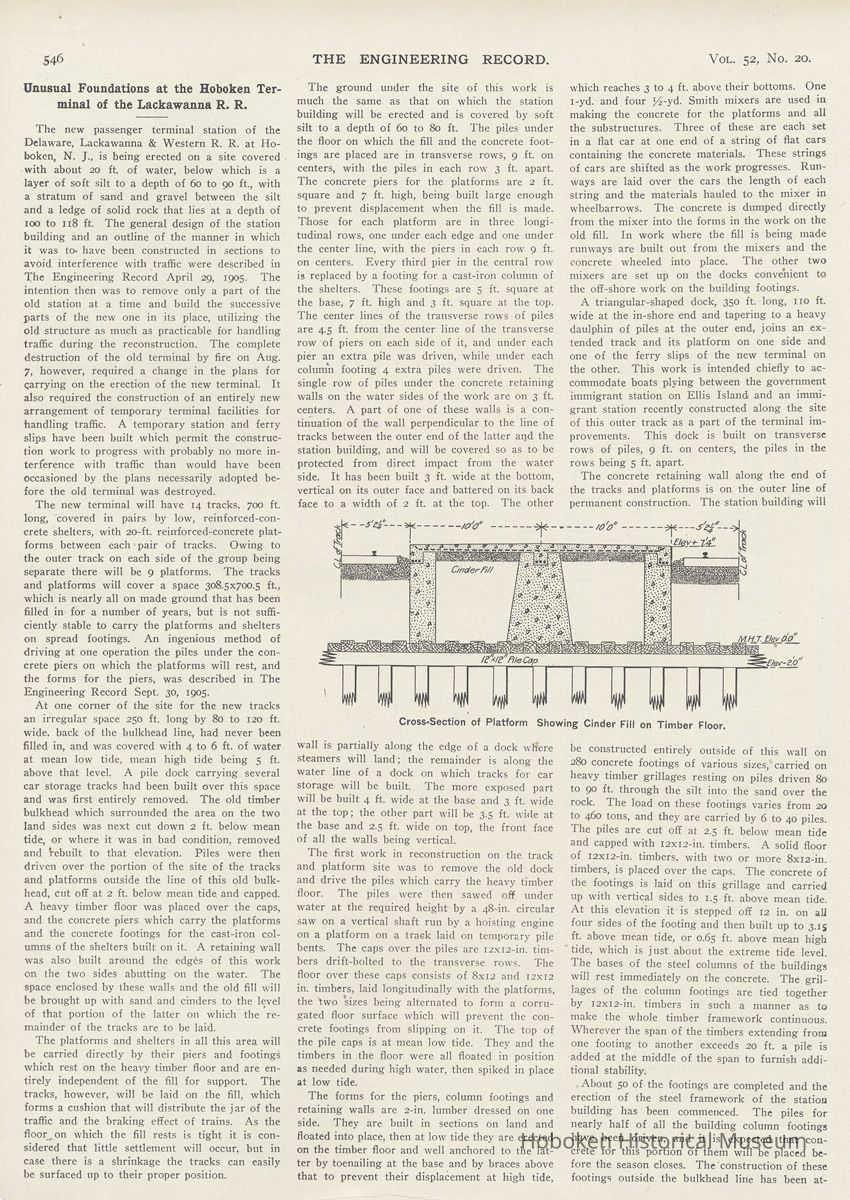
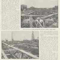
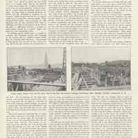
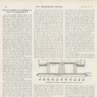
Notes: Archives 2012.007.0055 The Engineering Record, Volume 52, No. 20, November 11, 1905, pages 546-548. Full text of this article only. Unusual Foundations at the Hoboken Terminal of the Lackawanna R. R. The new passenger terminal station of the Delaware, Lackawanna & Western R. R. at Hoboken, N. J., is being erected on a site covered with about 20 ft of water, below which is a layer of soft silt to a depth of 60 to 90 ft., with a stratum of sand and gravel between the silt and a ledge of solid rock that lies at a depth of 100 to 118 ft. The general design of the station building and an outline of the manner in which it was to- have been constructed in sections to avoid interference with traffic were described in The Engineering Record April 29, 1905. The intention then was to remove only a part of the old station at a time and build the successive parts of the new one in its place, utilizing the old structure as much as practicable for handling traffic during the reconstruction. The complete destruction of the old terminal by fire on Aug. 7, however, required a change in the plans for carrying on the erection of the new terminal. It also required the construction of an entirely new arrangement of temporary terminal facilities for handling traffic. A temporary station and ferry slips have been built which permit the construction work to progress with probably no more interference with traffic than would have been occasioned by the plans necessarily adopted before the old terminal was destroyed. The new terminal will have 14 tracks, 700 ft. long, covered in pairs by low, reinforced-concrete shelters, with 20-ft. reinforced-concrete platforms between each pair of tracks. Owing to the outer track on each side of the group being separate there will be 9 platforms. The tracks and platforms will cover a space 308.5x700.5 ft., which is nearly all on made ground that has been filled in for a number of years, but is not sufficiently stable to carry the platforms and shelters on spread footings. An ingenious method of driving at one operation the piles under the concrete piers on which the platforms will rest, and the forms for the piers, was described in The Engineering Record Sept. 30, 1905. At one corner of the site for the new tracks an irregular space 250 ft. long by 80 to 120 ft. wide, back of the bulkhead line, had never been filled in, and was covered with 4 to 6 ft. of water at mean low tide, mean high tide being 5 ft. above that level. A pile dock carrying several car storage tracks had been built over this space and was first entirely removed. The old timber bulkhead which surrounded the area on the two land sides was next cut down 2 ft. below mean tide, or where it was in bad condition, removed and Vebuilt to that elevation. Piles were then driven over the portion of the site of the tracks and platforms outside the line of this old bulkhead, cut off at 2 ft. below mean tide and capped. A heavy timber floor was placed over the caps, and the concrete piers which carry the platforms and the concrete footings for the cast-iron columns of the shelters built on it. A retaining wall was also built around the edg£s of this work on the two sides abutting on the water. The space enclosed by these walls and the old fill will be brought up with sand and cinders to the level of that portion of the latter on which the remainder of the tracks are to be laid. The platforms and shelters in all this area will be carried directly by their piers and footings which rest on the heavy timber floor and are entirely independent of the fill for support. The tracks, however, will be laid on the fill, which forms a cushion that will distribute the jar of the traffic and the braking effect of trains. As the floor, on which the fill rests is tight it is considered that little settlement will occur, but in case there is a shrinkage the tracks can easily be surfaced up to their proper position. The ground under the site of this work is much the same as that on which the station building will be erected and is covered by soft silt to a depth of 60 to 80 ft. The piles under the floor on which the fill and the concrete footings are placed are in transverse rows, 9 ft. on centers, with the piles in each row 3 ft. apart. The concrete piers for the platforms are 2 ft. square and 7 ft. high, being built large enough to prevent displacement when the fill is made. Those for each platform are in three longitudinal rows, one under each edge and one under the center line, with the piers in each row 9 ft. on centers. Every third pier in the central row is replaced by a footing for a cast-iron column of the shelters. These footings are 5 ft. square at the base, 7 ft. high and 3 ft. square at the top. The center lines of the transverse rows of piles are 4.5 ft. from the center line of the transverse row of piers on each side of it, and under each pier an extra pile was driven, while under each column footing 4 extra piles were driven. The single row of piles under the concrete retaining walls on the water sides of the work are on 3 ft. centers. A part of one of these walls is a continuation of the wall perpendicular to the line of tracks between the outer end of the latter and the station building, and will be covered so as to be protected from direct impact from the water side. It has been built 3 ft. wide at the bottom, vertical on its outer face and battered on its back face to a width of 2 ft. at the top. The other [caption under diagram] Cross-Section of Platform Showing Cinder Fill on Timber Floor. wall is partially along the edge of a dock wlfere steamers will land; the remainder is along the water line of a dock on which tracks for car storage will be built. The more exposed part will be built 4 ft. wide at the base and 3 ft. wide at the top; the other part will be 3.5 ft. wide at the base and 2.5 ft. wide on top, the front face of all the walls being vertical. The first work in reconstruction on the track and platform site was to remove the old dock and drive the piles which carry the heavy timber floor. The piles were then sawed off under water at the required height by a 48-in. circular saw on a vertical shaft run by a hoisting engine on a platform on a track laid on temporary pile bents. The caps over the piles are I2xi2-in. timbers drift-bolted to the transverse rows. The floor over these caps consists of 8x12 and 12x12 in. timbers, laid longitudinally with the platforms, the two sizes being alternated to form a corrugated floor surface which will prevent the concrete footings from slipping on it. The top of the pile caps is at mean low tide. They and the timbers in the floor were all floated in position as needed during high water, then spiked in place The forms for the piers, column footings and retaining walls are 2-in. lumber dressed on one side. They are built in sections on land and floated into place, then at low tide they are erected on the timber floor and well anchored to the latter by toenailing at the base and by braces above that to prevent their displacement at high tide, which reaches 3 to 4 ft. above their bottoms. One 1-yd. and four 1/2-yd. Smith mixers are used in making the concrete for the platforms and all the substructures. Three of these are each set in a flat car at one end of a string of flat cars containing the concrete materials. These strings of cars are shifted as the work progresses. Runways are laid over the cars the length of each string and the materials hauled to the mixer in wheelbarrows. The concrete is dumped directly from the mixer into the forms in the work on the old fill. In work where the fill is being made runways are built out from the mixers and the concrete wheeled into place. The other two mixers are set up on the docks convenient to the off-shore work on the building footings. A triangular-shaped dock, 350 ft. long, no ft. wide at the in-shore end and tapering to a heavy daulphin of piles at the outer end, joins an extended track and its platform on one side and one of the ferry slips of the new terminal on the other. This work is intended chiefly to accommodate boats plying between the government immigrant station on Ellis Island and an immigrant station recently constructed along the site of this outer track as a part of the terminal improvements. This dock is built on transverse rows of piles, 9 ft. on centers, the piles in the rows being 5 ft. apart. The concrete retaining wall along the end of the tracks and platforms is on the outer line of permanent construction. The station building will be constructed entirely outside of this wall on 280 concrete footings of various sizes, carried on heavy timber grillages resting on piles driven 80 to 90 ft. through the silt into the sand over the rock. The load on these footings varies from 20 to 460 tons, and they are carried by 6 to 40 piles. The piles are cut off at 2.5 ft. below mean tide and capped with 12x12-in. timbers. A solid floor of 12x12-in. timbers, with two or more 8x12-in. timbers, is placed over the caps. The concrete of the footings is laid on this grillage and carried up with vertical sides to 1.5 ft. above mean tide. At this elevation it is stepped off 12 in. on all four sides of the footing and then built up to 3.15 ft. above mean tide, or 0.65 ft. above mean high "tide, which is just about the extreme tide level. The bases of the steel columns of the buildings will rest immediately on the concrete. The grillages of the column footings are tied together by 12x12-in. timbers in such a manner as to make the whole timber framework continuous. Wherever the span of the timbers extending from one footing to another exceeds 20 ft. a pile is added at the middle of the span to furnish additional stability. About 50 of the footings are completed and the erection of the steel framework of the station building has been commenced. The piles for nearly half of all the building column footings have been driven, and it is expected that concrete for this portion of them will be placed before the season closes. The construction of these footings outside the bulkhead line has been at- page 547 tended with considerable difficulty. A few of the piles were driven by drivers mounted on platforms running on tracks laid on the temporary pile bents. Most of them, however, have been driven by four floating drivers with extra long leads. The greater part of the piles are over 80 ft. long. They drive extremely easy at the start, but as thfir points approach the sand under the silt they resist driving sufficiently to give good supporting power. They are sawed off by the mounted circular saw used on other parts of the work, and the cap and grillage timbers drift-bolted in place during low water. The holes in these timbers for the drift bolts are made by bits driven by compressed air, which is supplied by a compressor plant mounted op a scow. The concrete forms are securely anchored to the grillage timbers. The concrete is wheeled to them from the mixers on plank runways laid on temporary bents built up from the timbers. The concrete for all this work is being mixed very wet in the proportions of 1 of Atlas Portland cement, 2 of sand and 3 of broken stone, with the dust screened out, that will pass through a 2-in. screen. The forms on the concrete in the filled ground are removed in 48 hours after the concrete is placed, if necessary. Those on the concrete exposed directly to the water will be left on all winter to insure protection to their surfaces against ice until they are completely set. The water around the site is very heavily charged with sewage, but it has been determined from other structures in the vicinity that concrete laid in it, when properly mixed and placed and when made sufficiently rich, has not been affected by the presence of the sewage in two years. The foundation work on the terminal will involve the driving of more than 13,000 piles for permanent construction, while a large amount of temporary piling is required to carry on the various pa'rts of the work. The piles in docks which [caption under lower left photo] A Portion of the Concrete Footings for Station Building Columns. Looking Off-Shore. have been built for at least 30 years and are now being removed to make room for the new work are apparently as sound as when driven, it being considered the sewage has prevented the action of the teredo. The accurate placing of each of the piles in the new work has been attended with special difficulty, since the reference base line had to be established back of the outer line of permanent construction and all centers off shore measured out from that line by triangulation. The foundation work on the terminal is being carried on by the regular forces of the Delaware, Lackawanna & Western R. R., Mr. L. Bush, chief engineer. Mr. J. E. Snell, superintendent of the department of buildings and docks, has general supervision of the work, which is under the immediate direction of Mr. F. L. Wheaton, assistant [caption under upper right photo] Part of the Forms for Concrete Retaining Walls and Column Footings. Looking In-Shore. engineer. The plans for the foundation and all of the substructure work were developed under the direction of Mr. G. T. Hand, assistant engineer. [end of this article] page 648 [caption for two photos across page center] Laying Heavy Timber Floor on Pile Caps; Part of the Piers and Column Footings, Floored-Over Area, Hoboken Terminal, Lackawanna R. R. Status: OK Status By: dw Status Date: 2012-03-22


